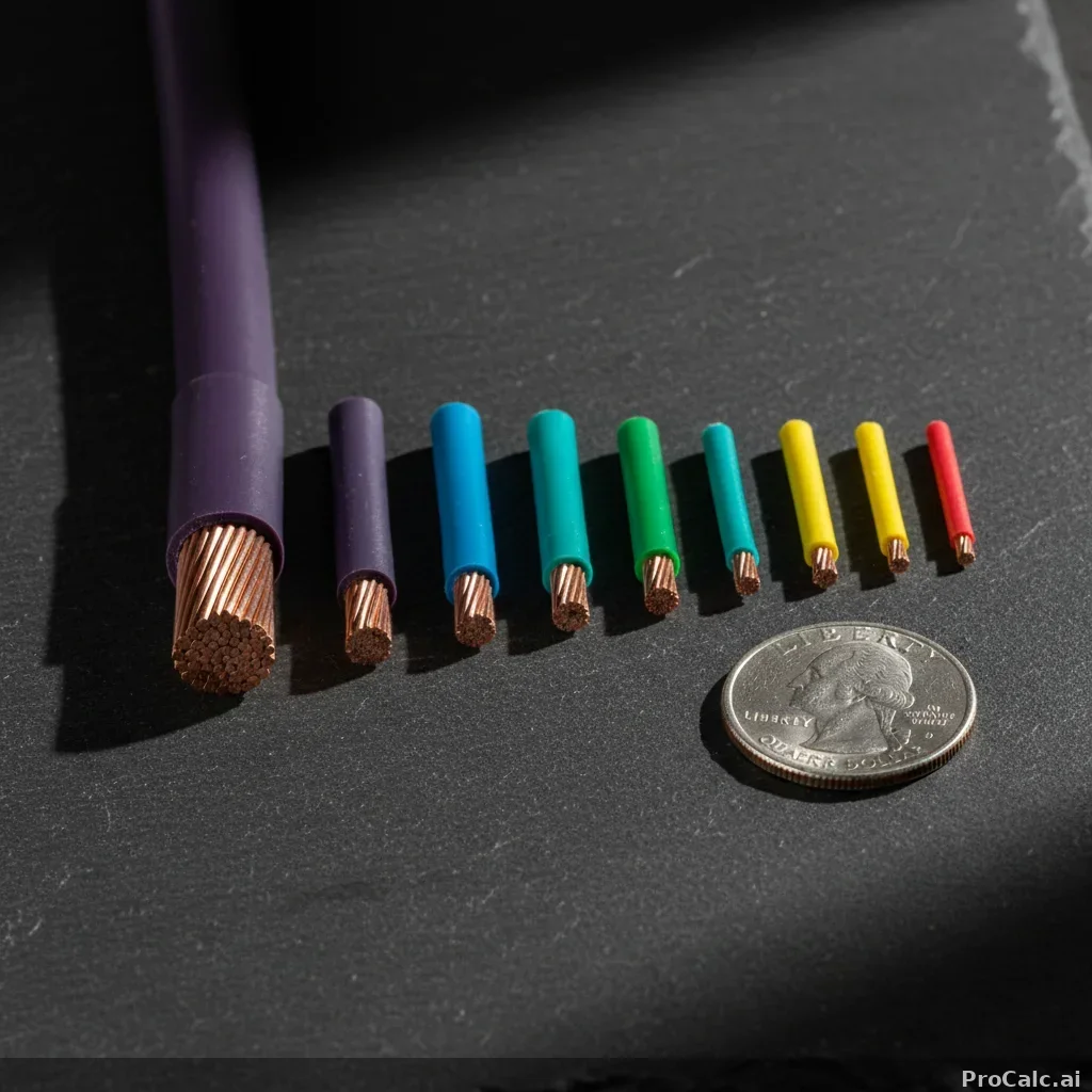
AWG 8
50A capacity · 3.264 mm
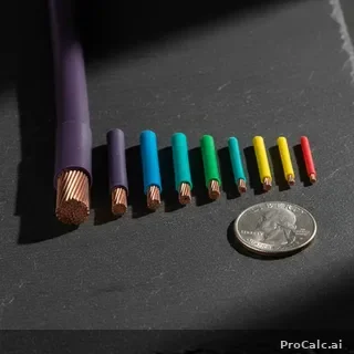
Wire Cross-Sections


| AWG / kcmil | 60°C | 75°C | 90°C | R (Ω/kft) | V-drop |
|---|---|---|---|---|---|
| 14 | 15 | 20 | 25 | 3.14 | 7.8% |
| 12 | 20 | 25 | 30 | 1.98 | 5.0% |
| 10 | 30 | 35 | 40 | 1.24 | 3.1% |
| 8 | 40 | 50 | 55 | 0.778 | 1.9% |
| 6 | 55 | 65 | 75 | 0.491 | 1.2% |
| 4 | 70 | 85 | 95 | 0.308 | 0.8% |
| 3 | 85 | 100 | 115 | 0.245 | 0.6% |
| 2 | 95 | 115 | 130 | 0.194 | 0.5% |
What is AWG?
The American Wire Gauge (AWG) system is a logarithmic stepped standardized wire gauge system used since 1857 for the diameters of round, solid, nonferrous, electrically conducting wire. AWG numbers are inversely related to wire diameter — a smaller AWG number means a larger wire. The scale runs from 0000 (4/0) as the largest standard AWG size down to 40 AWG for the thinnest. For conductors larger than 4/0, sizes are specified in kcmil (thousand circular mils). One kcmil equals a circular area of one mil (0.001 inch) diameter — so 250 kcmil is roughly equivalent to a wire 0.5 inches across.
How to Read NEC Table 310.16
NEC Table 310.16 lists allowable ampacities for insulated conductors rated up to 2000 volts, in an ambient temperature of 30°C (86°F), with no more than 3 current-carrying conductors in a raceway or cable. The table has three temperature columns (60°C, 75°C, and 90°C) corresponding to insulation types. TW insulation is rated 60°C, THW and THWN are 75°C, and THHN and XHHW are 90°C. The copper and aluminum/copper-clad aluminum sections have separate ampacity values. Equipment termination temperature limits (NEC 110.14(C)) often restrict which column you can actually use for sizing.
Voltage Drop: The Hidden Limit
While NEC Table 310.16 determines the maximum current a wire can safely carry based on heat, voltage drop is the other critical factor. Even when a wire passes the ampacity test, long runs can lose enough voltage that equipment malfunctions. NEC recommends no more than 3% voltage drop on branch circuits and 5% total for feeder plus branch combined. For single-phase circuits, voltage drop equals 2 × length × resistance × current ÷ 1000. For three-phase circuits, replace the factor of 2 with √3 (1.732). This calculator uses DC resistance from NEC Chapter 9, Table 8 at 75°C.
Copper vs Aluminum
Copper has about 61% higher conductivity than aluminum, meaning aluminum wire must be larger to carry the same current. However, aluminum is roughly one-third the weight and significantly cheaper per ampere of capacity. NEC treats aluminum and copper-clad aluminum (CCA) identically for ampacity ratings. CCA has an aluminum core with approximately 10% copper cladding for better termination compatibility. For large feeders and service entrance conductors (4/0 and above), aluminum is commonly used due to cost and weight savings. All terminations must be rated AL/CU or CU/AL for aluminum connections.
Common Residential Circuits
15A circuits use 14 AWG wire for general lighting. 20A circuits use 12 AWG for kitchen and bathroom outlets. 30A circuits use 10 AWG for electric dryers. 40A circuits use 8 AWG for electric ranges. 50A circuits use 6 AWG for EV Level 2 chargers. 100A sub-panels typically use 2 AWG or 1 AWG. 200A residential service entrance uses 2/0 or 4/0 AWG depending on conductor material and run length. NEC 240.4(D) caps overcurrent protection at 15A for 14 AWG, 20A for 12 AWG, and 30A for 10 AWG copper — regardless of the wire's actual ampacity rating.
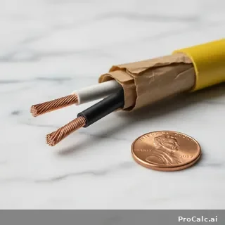
Wire Color Coding (NEC)
NEC requires specific colors for certain conductors: green or green with yellow stripe for equipment grounding, white or gray for grounded (neutral) conductors, and any other color for ungrounded (hot) conductors. By convention, black is the most common hot wire color in 120V circuits. Red is used for the second hot in 240V circuits. Blue and yellow are commonly used in commercial three-phase systems. Orange is used for 208V delta high-leg conductors. These colors help electricians quickly identify conductor function and maintain safety during installation and service.
Continuous vs Non-Continuous Loads
NEC defines a continuous load as one expected to operate at maximum current for 3 hours or more. Per NEC 210.19(A)(1)(a), conductor ampacity must be at least 125% of the continuous load plus 100% of the non-continuous load. This 125% rule accounts for heat buildup during extended operation. Common continuous loads include commercial lighting, data center servers, electric baseboard heaters, and EV charging. A 30A continuous load requires a conductor rated for at least 37.5A. This is why this calculator applies the 1.25 multiplier when recommending wire sizes.
Temperature Derating
NEC Table 310.15(B)(1) provides correction factors for ambient temperatures above 30°C (86°F). In hot environments like attics, rooftops, or near industrial equipment, conductor ampacity must be reduced. The 90°C column is primarily used as a starting point for derating calculations — you derate from the 90°C value, then confirm the result doesn't exceed the 75°C column value (since most terminations are rated 75°C). This two-step process lets you take advantage of higher-rated insulation while respecting equipment limitations.
Conduit Fill Considerations

When more than 3 current-carrying conductors are in a single raceway, NEC Table 310.15(C)(1) requires ampacity adjustment. With 4-6 conductors, derate to 80% of table values. With 7-9, derate to 70%. This stacking factor combines with temperature derating. Conduit fill limits (NEC Chapter 9, Table 1) restrict how many wires can physically fit: 1 wire uses 53% fill, 2 wires use 31%, and 3+ wires use 40% of conduit cross-sectional area. These rules prevent overheating from conductors being too close together with inadequate air circulation.
Related Calculators
About the Wire Gauge Calculator
The ProCalc.ai Wire Gauge Calculator helps you choose an AWG wire size that can safely carry your load without excessive voltage drop. You use the Wire Gauge Calculator when you’re sizing conductors for DC runs, low-voltage controls, or power distribution where distance matters as much as current. Electrical engineers, panel builders, and industrial maintenance techs rely on this kind of quick check to avoid nuisance trips, dimming, and overheated conductors during commissioning. Picture a 12 V pump mounted 40 feet from its battery bank on a skid: pick too small a cable and the motor struggles at startup, pick too large and you waste cost and space in the tray. The workflow is simple: you enter the circuit current and the one-way or total run distance, and you get a recommended AWG wire size based on typical ampacity and voltage-drop assumptions. Use the result as a starting point, then confirm against your project’s insulation rating, ambient temperature, bundling, and applicable code requirements before you finalize the spec.
How does the wire gauge calculator work?
The wire gauge calculator computes results instantly by applying standard engineering formulas to the values entered into its input fields. No sign-up is required; results appear immediately as you type.
What Is the Wire Gauge Calculator?
The Wire Gauge Calculator sizes electrical conductor based on amperage, run length, voltage, and acceptable voltage drop. It returns the minimum AWG (American Wire Gauge) for the load, factors in NEC ampacity tables, and flags upsizing needed for long runs where voltage drop exceeds the recommended 3% branch / 5% feeder limit.
How to Use This Calculator
Enter the load current in amps, the one-way distance in feet, the supply voltage (usually 120 V or 240 V residential, 480 V three-phase commercial), and target voltage drop percentage. Pick conductor material — copper is the default; aluminum needs to go up two AWG sizes for the same ampacity. The output shows the smallest gauge that satisfies both ampacity and voltage drop, plus the next size up as a margin recommendation.
Common Use Cases
- Detached garage subpanel: 60 A, 100 ft from the main, 240 V — copper jumps from 6 AWG (ampacity-fine) to 4 AWG to keep voltage drop under 3%.
- Pool pump motor: Long runs to outdoor equipment frequently fail voltage drop before they fail ampacity; the calculator catches this immediately.
- EV charger circuit: A 48 A continuous load needs 60 A breaker (125% rule) and 6 AWG copper, but at 75 ft the conductor often needs to be upsized to 4 AWG.
- RV park pedestal feeders: 50 A service at 200 ft from the panel almost always needs 2 AWG aluminum or 4 AWG copper.
Understanding the Results
Ampacity comes from NEC Table 310.16, derated for ambient temperature and conductor count when applicable. Voltage drop is calculated from conductor resistance per 1,000 ft, doubled for the round-trip current path. Continuous loads (3 hours or more) require the conductor and breaker to be sized at 125% per NEC 210.19(A)(1).
Industry Standards and Tips
The NEC recommends 3% maximum voltage drop on branch circuits and 5% combined on feeder + branch — these are recommendations, not code violations, but exceeding them shortens motor life and dims lighting. Always verify the breaker rating matches the conductor's terminal temperature rating (usually 60°C for residential under 100 A, 75°C for larger). When in doubt, upsize one gauge — copper price is cheap insurance against future load growth.
For motor-specific sizing, see the Voltage Drop Calculator.
Wire Gauge Calculator — Frequently Asked Questions(8)
Common questions about wire gauge.
Last updated Apr 2026
What the Wire Gauge Calculator does (and why it matters)
A Wire Gauge Calculator helps you choose an American Wire Gauge (AWG) size that keeps voltage drop within a target limit for a given circuit. If the wire is too small, resistance causes a bigger voltage drop, which can lead to dim lights, slow motors, nuisance trips, overheating, and equipment not meeting its rated performance.
This calculator is built around voltage-drop sizing: you enter Current (Amps), One-Way Distance (ft), System Voltage, and Max Voltage Drop (%), and it returns a recommended AWG size plus the estimated voltage drop.
Important: This tool sizes wire based on voltage drop only. Real-world wire selection must also satisfy ampacity (thermal limits), insulation temperature rating, installation method, ambient temperature, bundling, and code requirements.
Inputs you’ll need
1. Current (Amps) The expected load current. For continuous loads, many standards require using 125% of the continuous current when selecting conductors; if that applies to your project, enter the adjusted current.
2. One-Way Distance (ft) The physical length from source to load in one direction. The calculator internally doubles it to account for the round-trip path (out and back).
3. System Voltage Common values are 12, 24, 48, 120, 240, 277, 480, etc. Lower voltage systems are much more sensitive to voltage drop.
4. Max Voltage Drop (%) A typical design target is 3% for a branch circuit, but your application may differ. Smaller percent means thicker wire.
The calculation logic (step-by-step)
The calculator uses a simplified voltage drop model for copper conductors based on circular mil area. Here’s the exact logic in plain language.
### Step 1) Convert max drop percent to allowable voltage drop (volts)
Let:
- \( a \) = current in amps - \( d \) = one-way distance in feet - \( v \) = system voltage - \( md \) = max drop percent as a decimal
\[ md = \frac{\text{Max Voltage Drop (\%)}}{100} \] \[ \text{Allowable Drop (V)} = v \times md \]
So if voltage is 120 and max drop is 3%:
\[ \text{Allowable Drop} = 120 \times 0.03 = 3.6 \text{ V} \]
### Step 2) Compute the minimum required conductor area (circular mils)
The calculator estimates the minimum circular mil area needed:
\[ \text{Min CMIL} = \frac{2 \times d \times a \times 10.8}{\text{Allowable Drop (V)}} \]
Where: - The factor \(2 \times d\) accounts for round-trip length. - 10.8 is a copper resistivity constant used in common voltage-drop approximations with circular mils and feet.
The result is Min CMIL (minimum circular mil area). Bigger CMIL means thicker wire.
### Step 3) Map Min CMIL to the next AWG size up
The calculator compares Min CMIL to a built-in AWG table (circular mil areas). It chooses the first wire size whose circular mil area is greater than or equal to Min CMIL.
Key table points used:
- 14 AWG = 4,110 CMIL - 12 AWG = 6,530 CMIL - 10 AWG = 10,380 CMIL - 8 AWG = 16,510 CMIL - 6 AWG = 26,240 CMIL - 4 AWG = 41,740 CMIL - 2 AWG = 66,360 CMIL - 1 AWG = 83,690 CMIL - 0 AWG = 105,600 CMIL - 00 AWG = 133,100 CMIL - 000 AWG = 167,800 CMIL
If Min CMIL is small, the calculator floors at 14 AWG (it won’t recommend smaller than 14 AWG).
### Step 4) Calculate the estimated actual voltage drop (%)
Using the selected wire’s circular mil area \(cmil\):
\[ \text{Drop \%} = \left(\frac{2 \times d \times a \times 10.8}{cmil}\right)\div v \times 100 \]
The calculator reports this as Actual Voltage Drop (%) (rounded to 2 decimals).
Worked examples (using the calculator’s exact method)
### Example 1: 20 A, 50 ft one-way, 120 V, 3% max drop
Inputs: - Current \(a = 20\) A - Distance \(d = 50\) ft - Voltage \(v = 120\) - Max drop \(= 3\%\)
1) Allowable drop: \[ \text{Allowable Drop} = 120 \times 0.03 = 3.6 \text{ V} \]
2) Min CMIL: \[ \text{Min CMIL} = \frac{2 \times 50 \times 20 \times 10.8}{3.6} = \frac{21,600}{3.6} = 6,000 \]
3) Choose AWG: - 14 AWG is 4,110 CMIL (too small) - 12 AWG is 6,530 CMIL (meets 6,000)
Recommended: 12 AWG
4) Actual drop % with 12 AWG (6,530 CMIL): \[ \text{Drop \%} = \left(\frac{21,600}{6,530}\right)\div 120 \times 100 \approx 2.76\% \]
So you’re under the 3% target.
### Example 2: 30 A, 100 ft one-way, 240 V, 3% max drop
Inputs: - \(a = 30\) A, \(d = 100\) ft, \(v = 240\), \(md = 0.03\)
1) Allowable drop: \[ 240 \times 0.03 = 7.2 \text{ V} \]
2) Min CMIL: \[ \text{Min CMIL} = \frac{2 \times 100 \times 30 \times 10.8}{7.2} = \frac{64,800}{7.2} = 9,000 \]
3) Choose AWG: - 12 AWG = 6,530 (too small) - 10 AWG = 10,380 (meets 9,000)
Recommended: 10 AWG
4) Actual drop % with 10 AWG (10,380 CMIL): \[ \text{Drop \%} = \left(\frac{64,800}{10,380}\right)\div 240 \times 100 \approx 2.60\% \]
### Example 3: 15 A, 150 ft one-way, 120 V, 3% max drop
Inputs: - \(a = 15\) A, \(d = 150\) ft, \(v = 120\), max drop 3%
1) Allowable drop: \[ 120 \times 0.03 = 3.6 \text{ V} \]
2) Min CMIL: \[ \text{Min CMIL} = \frac{2 \times 150 \times 15 \times 10.8}{3.6} = \frac{48,600}{3.6} = 13,500 \]
3) Choose AWG: - 10 AWG = 10,380 (too small) - 8 AWG = 16,510 (meets 13,500)
Recommended: 8 AWG
4) Actual drop % with 8 AWG (16,510 CMIL): \[ \text{Drop \%} = \left(\frac{48,600}{16,510}\right)\div 120 \times 100 \approx 2.45\% \]
Long runs quickly push you into thicker wire even at modest current.
Pro Tips for better results
- Use realistic current, not just breaker rating. If a device draws 12 A, entering 20 A will oversize the wire for voltage drop (sometimes that’s fine, but know why you’re doing it). - For continuous loads, consider entering 125% of the expected continuous current to build in margin. - If you’re working with low-voltage systems (12 to 48 V), tighten the max drop carefully. Even 3% can be noticeable in performance, and wire sizes can jump fast. - Treat the result as a minimum for voltage drop. If the wire will be in hot environments, in conduit with many conductors, or carrying harmonics, you may need a larger size for ampacity and heat. - If you’re near a threshold (for example Min CMIL barely fits 12 AWG), consider stepping up one size to reduce heating and improve efficiency.
Common mistakes to avoid
- Entering round-trip distance instead of One-Way Distance (ft). The calculator already multiplies by 2 internally; doubling it again can oversize the wire significantly. - Forgetting that the tool is voltage-drop based and ignoring ampacity. A wire can meet voltage drop but still be undersized thermally depending on installation conditions. - Using the wrong System Voltage (for example entering 120 when the load is actually 240). Voltage drop percent depends on voltage; doubling voltage cuts the percent drop in half for the same wire and load. - Setting Max Voltage Drop (%) unrealistically low without realizing the cost/size impact. Going from 3% to 1% roughly triples the required circular mil area. - Assuming the recommendation applies to aluminum conductors. The constant used here is for copper; aluminum requires larger area for similar drop.
Quick interpretation of the output
- Recommended AWG: the smallest gauge in the calculator’s table that meets your voltage-drop target (with a minimum of 14 AWG). - Min CMIL: the computed minimum circular mil area needed to stay within the allowable drop. - Allowable Drop (V): the maximum voltage you can lose along the run based on your percent setting. - Actual Voltage Drop (%): the estimated drop using the selected wire size; it should be at or below your target.
Use the calculator to get a solid starting point, then confirm final conductor sizing against your applicable electrical code, insulation rating, and installation conditions.
Authoritative Sources
This calculator uses formulas and reference data drawn from the following sources:
- Purdue Engineering - MIT OpenCourseWare - EPA — Energy Resources
Wire Gauge Formula & Method
This wire gauge calculator uses standard engineering formulas to compute results. Enter your values and the formula is applied automatically — all math is handled for you. The calculation follows industry-standard methodology.
Wire Gauge Sources & References
Explore More Calculators
Content reviewed by the ProCalc.ai editorial team · About our standards
🔀 You Might Also Use
Mortgage Calculator
Free mortgage calculator with payment breakdown, amortization schedule, extra payment scenarios, and 15 vs 30 year comparison.
FINANCEBMI Calculator
Free BMI Calculator — Calculate BMI. Check if weight is healthy based on height. AI-powered health tool.
HEALTHAge Calculator
Free Age Calculator — Calculate your age in years, months, days. Find day of week you were born. Instant results.
MATHBMR Calculator
Free BMR calculator using Mifflin-St Jeor and Harris-Benedict formulas. Enter age, weight, and height to find calories burned at rest — instant results.
HEALTH📖 Related Articles
Copper vs Aluminum Wire: Weight, Ampacity, and When to Use Each
Aluminum wire carries the same current as copper at a larger gauge but weighs one-third as much. Here is the weight and ampacity comparison and when each conductor is the right choice.
10 min read
Understanding Wire Gauge: AWG Sizing, Resistance, and Ampacity
How AWG wire gauge determines resistance, current capacity, and voltage drop — and why getting it right matters for every electrical project.
6 min read